Demonstrators
The PowerizeD demonstrators showcase how digitalisation transforms power electronics across key application domains. Each use case validates innovative solutions that enhance efficiency, reliability, and sustainability, highlighting the project’s real-world impact and contribution to Europe’s green and digital transition.
UC 1.1 - Railway propulsion systems
by: Ganesh Chandramouli
from: Alstom Rail SWEDEN AB
Smart sensing functions in intelligent control and gate drive platform, replacing or augmenting discrete stand-alone sensors using capabilities built into the controller, gate drive, and power semiconductor. Test system and methods for AI enhanced verification of railway propulsion systems, improving reliability and robustness testing of power electronics.
UC 1.2 - Traction Converters
by: Inigo Polo
from: Ingeteam Power Technology SA

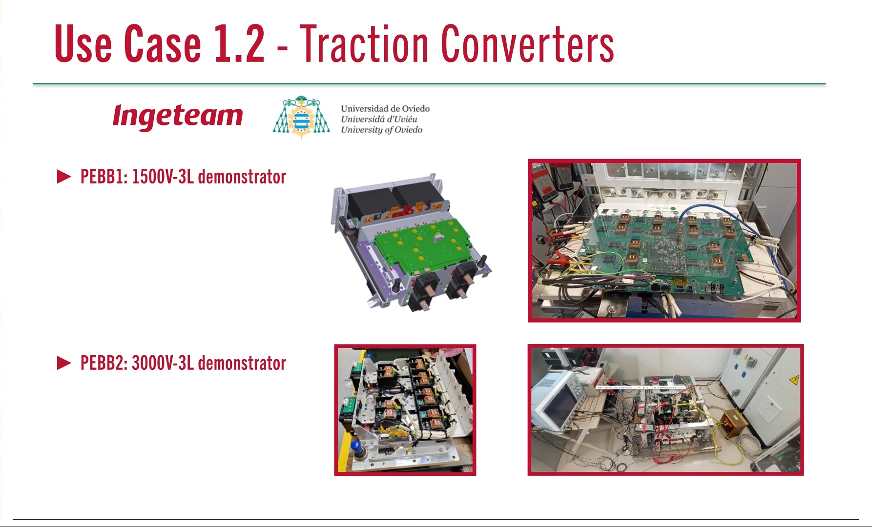
In this UC, two Demonstrators have been designed and manufactured for validation of new traction power systems in railway:
Demonstrator 1 (PEBB): The 1500V-3L demonstrator is designed for railway vehicles that operates at nominal 1,5KV DC catenary lines. The PEBB is based in semiconductor package XHP2, LV100 and ANPC topology. As ANPC is more complex than NPC, this PEBB integrates a PMM electronic board that will be connected to TCU. The versatility of this type of PEBB allows fast and custom power systems configurations for specific projects.
Demonstrator 2 (PEBB): The 3000V-3L demonstrator is designed for railway vehicles that operates at nominal 3KV DC catenary lines. The PEBB is based in new semiconductor package XHP3, HV100 and NPC topology. The versatility of this type of PEBB allows fast and custom power systems configurations for specific projects.
from: Ingeteam Power Technology SA
In this UC, two Demonstrators have been designed and manufactured for validation of new traction power systems in railway:
Demonstrator 1 (PEBB): The 1500V-3L demonstrator is designed for railway vehicles that operates at nominal 1,5KV DC catenary lines. The PEBB is based in semiconductor package XHP2, LV100 and ANPC topology. As ANPC is more complex than NPC, this PEBB integrates a PMM electronic board that will be connected to TCU. The versatility of this type of PEBB allows fast and custom power systems configurations for specific projects.
Demonstrator 2 (PEBB): The 3000V-3L demonstrator is designed for railway vehicles that operates at nominal 3KV DC catenary lines. The PEBB is based in new semiconductor package XHP3, HV100 and NPC topology. The versatility of this type of PEBB allows fast and custom power systems configurations for specific projects.
UC 1.3 - DC/DC Converters
by: Inigo Polo
from: Ingeteam Power Technology SA
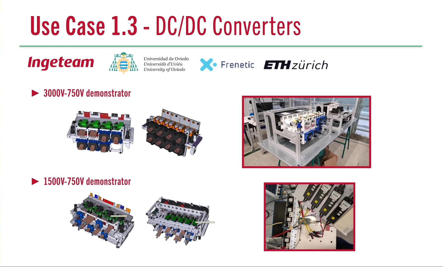
In this UC, two demonstrators have been designed and manufactured for validation of new auxiliary power systems in railway: Demonstrator 1 (PEBB): Bidirectional resonant converter has been designed to operate between 3kV on the high-voltage side and 750V on the low-voltage side. This system consists of a PEBB incorporating 3.3kV-rated IGBTs in multilevel-level configuration on the high-voltage side, and a second PEBB featuring 1.7kV-rated IGBTs in a two-level configuration on the low-voltage side. The conversion process relies on a medium-frequency transformer and a set of resonant capacitors, achieving 300kW from high voltage to low voltage and vice versa. “Photo demonstrator 1 of UC1.3” Demonstrator 2 (PEBB): Unidirectional resonant converter has been designed to operate between 1.5kV on the high-voltage side and 750V on the low-voltage side. In this configuration, the high-voltage side uses 1.7kV-rated IGBTs arranged in a multi-level topology, while the low-voltage side used the other face of the same PEBB, equipped with 1.2kV-rated IGBTs functioning as diodes in a two-level configuration. Similar to the first demonstrator, this system includes a medium-frequency transformer and a set of resonant capacitors achieving 100kW, only from high voltage to low voltage. “Photo demonstrator 2 of UC1.3”
from: Ingeteam Power Technology SA
In this UC, two demonstrators have been designed and manufactured for validation of new auxiliary power systems in railway: Demonstrator 1 (PEBB): Bidirectional resonant converter has been designed to operate between 3kV on the high-voltage side and 750V on the low-voltage side. This system consists of a PEBB incorporating 3.3kV-rated IGBTs in multilevel-level configuration on the high-voltage side, and a second PEBB featuring 1.7kV-rated IGBTs in a two-level configuration on the low-voltage side. The conversion process relies on a medium-frequency transformer and a set of resonant capacitors, achieving 300kW from high voltage to low voltage and vice versa. “Photo demonstrator 1 of UC1.3” Demonstrator 2 (PEBB): Unidirectional resonant converter has been designed to operate between 1.5kV on the high-voltage side and 750V on the low-voltage side. In this configuration, the high-voltage side uses 1.7kV-rated IGBTs arranged in a multi-level topology, while the low-voltage side used the other face of the same PEBB, equipped with 1.2kV-rated IGBTs functioning as diodes in a two-level configuration. Similar to the first demonstrator, this system includes a medium-frequency transformer and a set of resonant capacitors achieving 100kW, only from high voltage to low voltage. “Photo demonstrator 2 of UC1.3”
UC 1.4 - BEHDV Drive Inverter for High Voltage - Demo A
by:
from: SCANIA CV AB
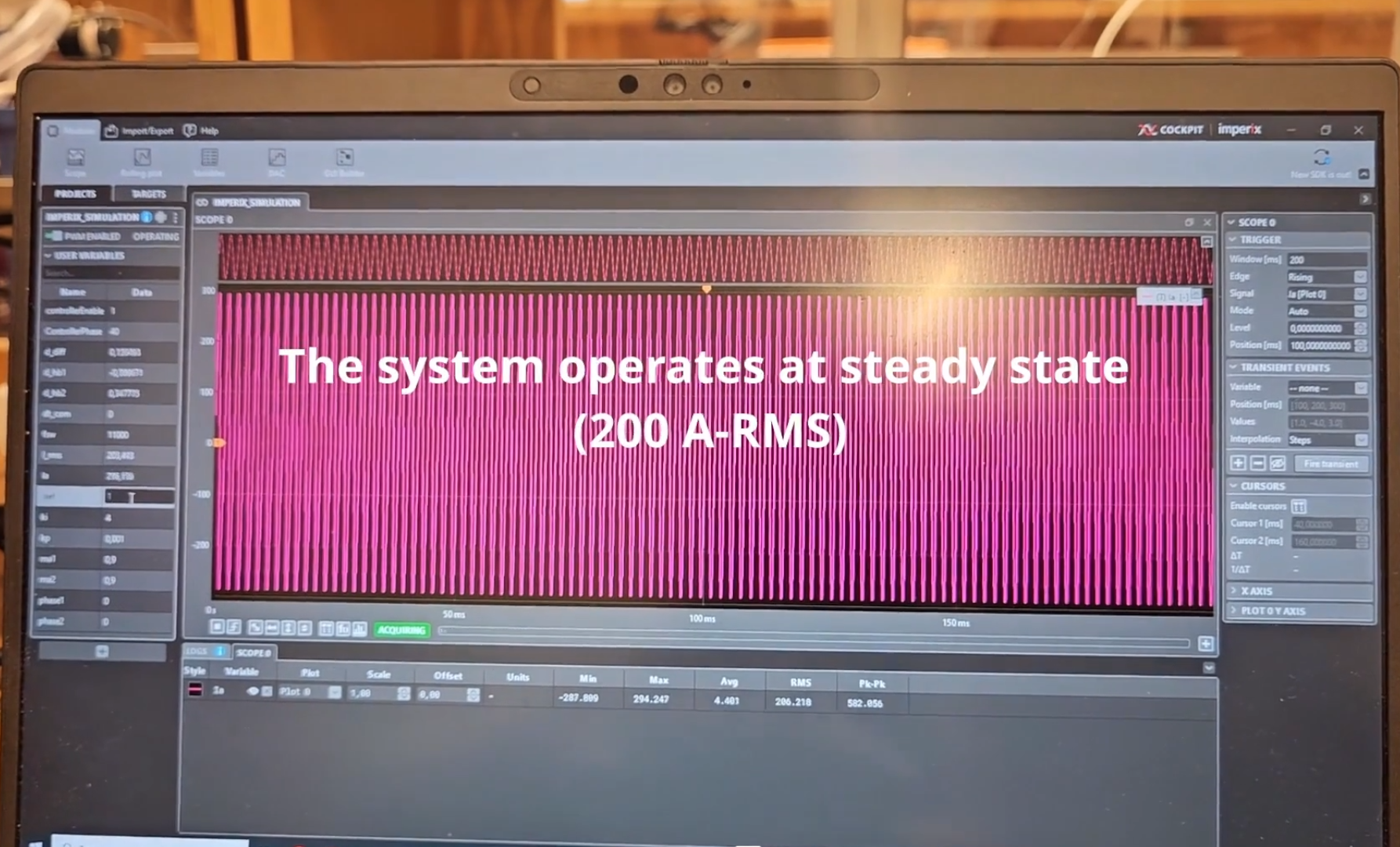
Back-to-Back Inverter Platform A back-to-back (B2B) inverter system has been developed toevaluate the performance of the designed traction inverter undercontrolled laboratory conditions. The setup connects two SiC-basedinverters through a common DC-link, enabling circulation ofcurrent without the need for a motor or high-power supply. Thisdemonstrator allows testing of switching behavior, PWM strategies,phase current control, and DC-link operation across a wide rangeof operating points. “Photo demonstrator 2 of UC1.3”
from: SCANIA CV AB
Back-to-Back Inverter Platform A back-to-back (B2B) inverter system has been developed toevaluate the performance of the designed traction inverter undercontrolled laboratory conditions. The setup connects two SiC-basedinverters through a common DC-link, enabling circulation ofcurrent without the need for a motor or high-power supply. Thisdemonstrator allows testing of switching behavior, PWM strategies,phase current control, and DC-link operation across a wide rangeof operating points. “Photo demonstrator 2 of UC1.3”
UC 1.4 - BEHDV Drive Inverter for High Voltage - Demo B
by:
from: SCANIA CV AB
Calorimetric Loss-Measurement Setup
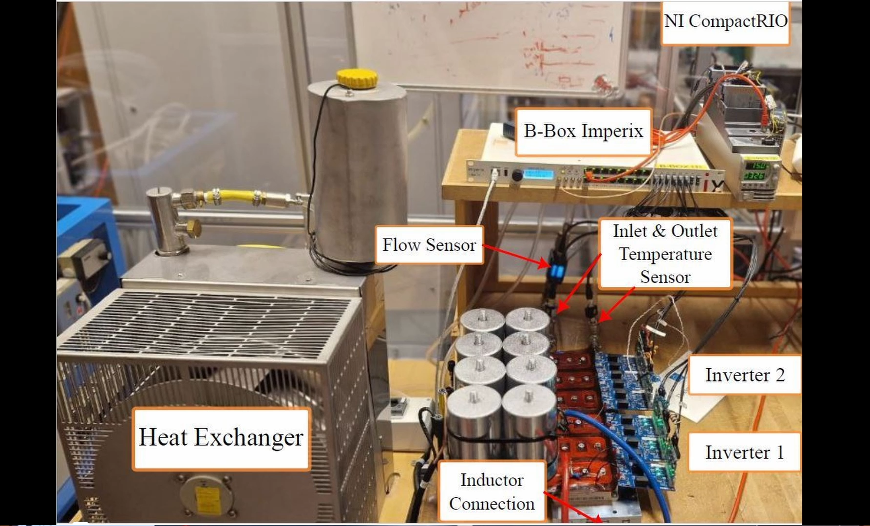
A dedicated calorimetric testbench has been built to preciselyestimate inverter losses during operation. The setup isolates theinverters thermally and measures heat dissipation with highaccuracy, enabling reliable efficiency assessment at differentswitching frequencies, load conditions, and modulation schemes.This demonstrator complements the B2B platform by providinghigh-precision validation of loss measurements.
from: SCANIA CV AB
Calorimetric Loss-Measurement Setup
A dedicated calorimetric testbench has been built to preciselyestimate inverter losses during operation. The setup isolates theinverters thermally and measures heat dissipation with highaccuracy, enabling reliable efficiency assessment at differentswitching frequencies, load conditions, and modulation schemes.This demonstrator complements the B2B platform by providinghigh-precision validation of loss measurements.
UC 1.5 - FCEV - Fuel cell and powertrain inverter - Demo A

by: Akshay Panchwagh
from: Robert Bosch GmbH
In this use case, a Multi Chip Power Package (MCPP) equipped with a piezoresistive silicon-based stress sensor was used as a demonstrator to highlight the methodology of virtual release through referencing for reduction in development time. For this purpose, two different constructions of the MCPP were used – a B2 bridge and a B6 bridge. The B2 bridge was subjected to passive operating conditions, in which the power package remains inactive while the environmental conditions vary, and the B6 bridge, attached to a cooler, was subjected to active operating conditions in which the power package is actively powered. The aim of using such operating conditions was an accelerated replication of the field conditions, in which the power package operates, and to test the response of the MCPP to such conditions. The demonstrators (B2 and B6 bridges), both equipped with an over-molded piezoresistive stress sensor, (called the iForce sensor) were used to analyze their thermomechanical response to the applied loading conditions and measure stress states within the power package during operations. During both the operations, the warpage response using a Digital Image Correlation (DIC) method, and stresses in the package with the help of iForce sensor were measured. The iForce sensor is a piezoresistive stress sensor, as mentioned previously, which consists of a silicon die of size 1,67 mm x 1,71 mm placed on a Low Temperature Co-Fired Ceramic (LTCC) substrate. Through usage of gold bond wires, it is connected to copper pillars, or pins which help in controlling the sensing cells of the sensor. The sensor used in the demonstrator here has 36 sensing cells. These cells measure stresses in the package with the help of piezoresistive effect of silicon, in which its electrical resistivity changes upon application of stresses. The change is resistivity leads to change in the electrical current which flows through the sensor. The change in these current values helps to calculate the stresses within the package. The aim of measuring these responses was to draw comparisons between experimentally measured values, and their virtual responses to help validate the simulation models, which will be used subsequently as “credible” simulation models.
A B2-Bridge used for combined Warpage-and-Stress Measurement. Cables are connected to Pins of iForce Sensor to extract Stress Data.
A Combined Warpage-and-Stress Measurement of a B2-Bridge During Passive Temperature Cycling.
A B6-Bridge on Cooler with iForce Sensor Pins Visible.
UC 1.5 - FCEV - Fuel cell and powertrain inverter - Demo B
by: Chrisitan Ohms
from: Mercedes Benz
The assembled inverter is derived from a universal platform developed at Mercedes-Benz. It consists of the power electronic semiconductor module, provided by project partner Bosch, a DC-link capacitor, current and voltage sensors, a liquid-cooled heatsink, a gate driver board and a controller board. The power module is a Bosch CSL-1200-355-PS module, capable of a continuous current of 355A and a maximum blocking voltage of 1200V, making it a suitable choice for appliances in automotive 800V-drivetrains. The DC-link capacitor has a total capacity of 600µF. The gate driver board is tailored for the Bosch EG120 driver chip, which allows to define a number of up to 133 different gate current profiles. This feature allows to select the most appropriate gate current profile for a large number of different operation points, with regard to switching losses and safe operation area. Finally, the demonstrator is equipped with a Texas Instruments C2000 microcontroller, a 32-bit dual CPU device with 200MHz clock, 2x512KB flash memory, numerous digital interfaces such as SPI, I2C, CAN, CAN FD and USB2.0, 32 PWM channels and four Analog-to-Digital converters with 24 single-ended inputs. The demonstrator serves as a platform for the PHM and digital twin algorithms developed by the project partners.
UC 1.6a - Mobile In-Line Charger
by: Stephan Thomas
from: AixControl GmbH
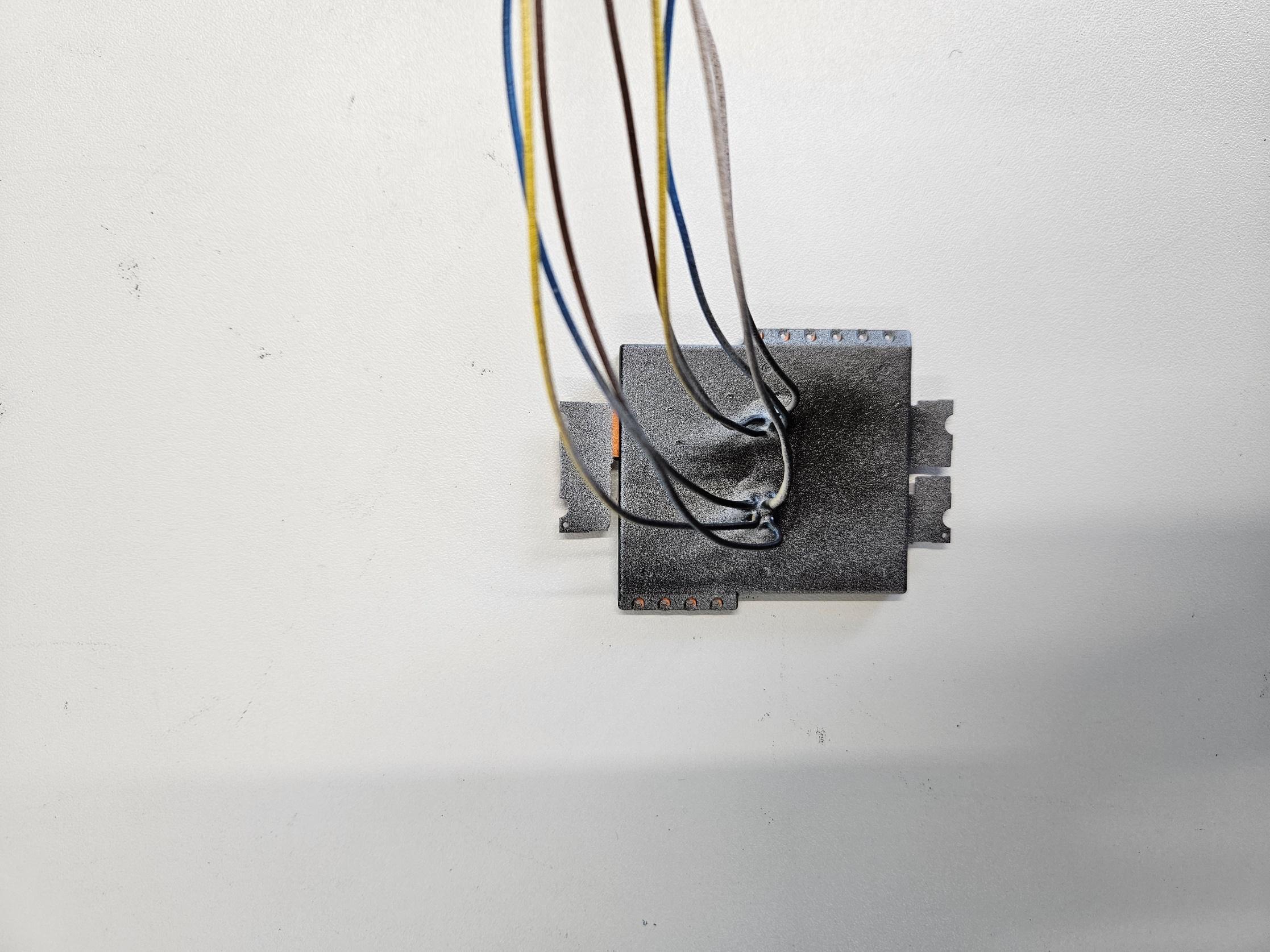
The Mobile In-Line Charger (MILCA) demonstrates a compact DC-charging solution for electric vehicles with a nominal charging power of approximately 2 kW. MILCA connects to a standard 230V house socket and has a CCS2 plug at the output for the connection to the electric vehicle. All components for DC charging, from contactors and insulation measurements to powerline communication(PLC), are integrated into a volume of approximately 2l. In this project, the focus was on the power electronics with a maximum volume of 1.5l. The MILCA has an integrated active power factor correction and a galvanically isolated DC/DC converter. The latest-generation of gallium nitride semiconductors make this compact charging electronics possible and might pave the way for future cars to dispense with build-in onboard chargers.![]()
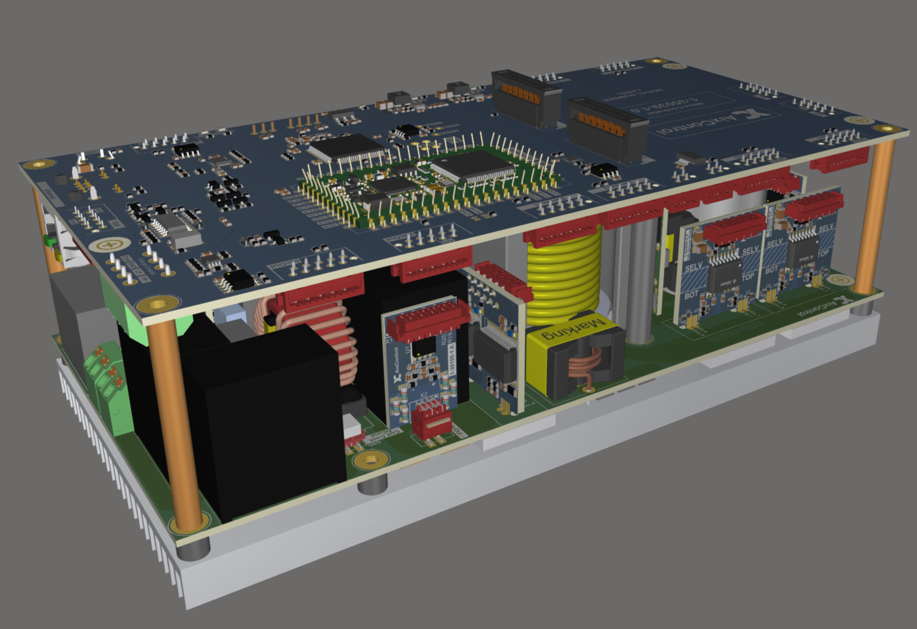 3D-design with low stray inductance connection of driver stages for GaN semiconductors.
![]()
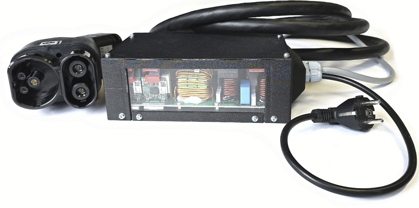
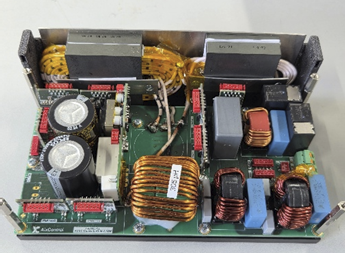 First prototype realization of the MILCA.
![]()
![]()
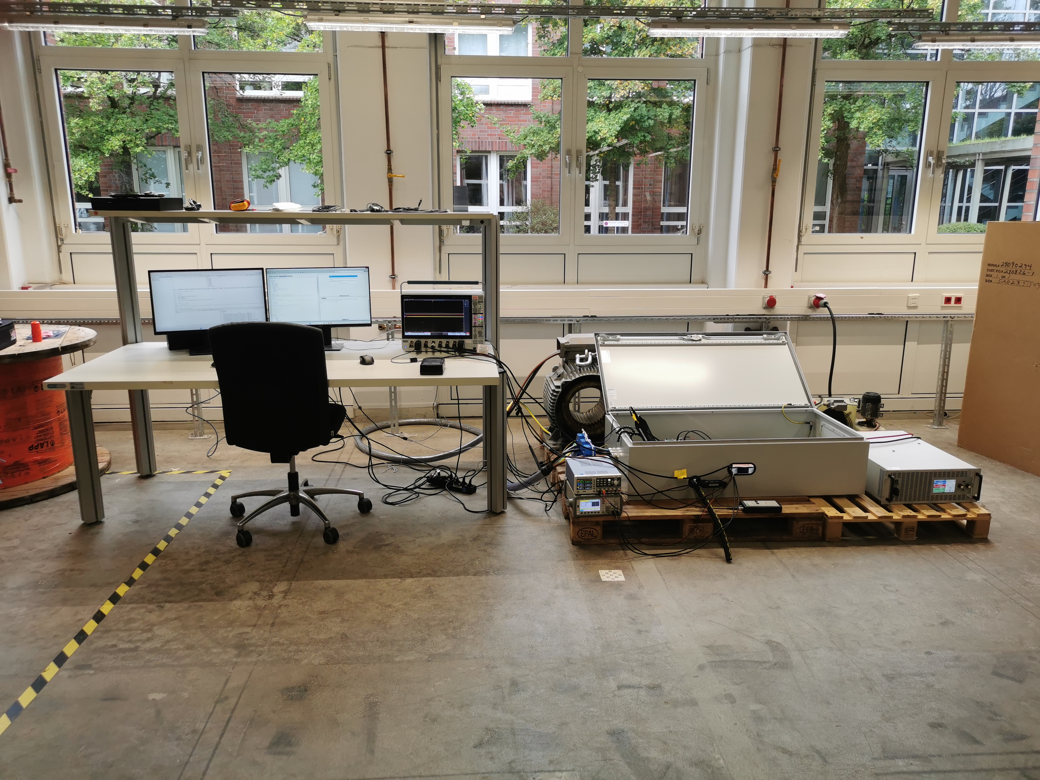
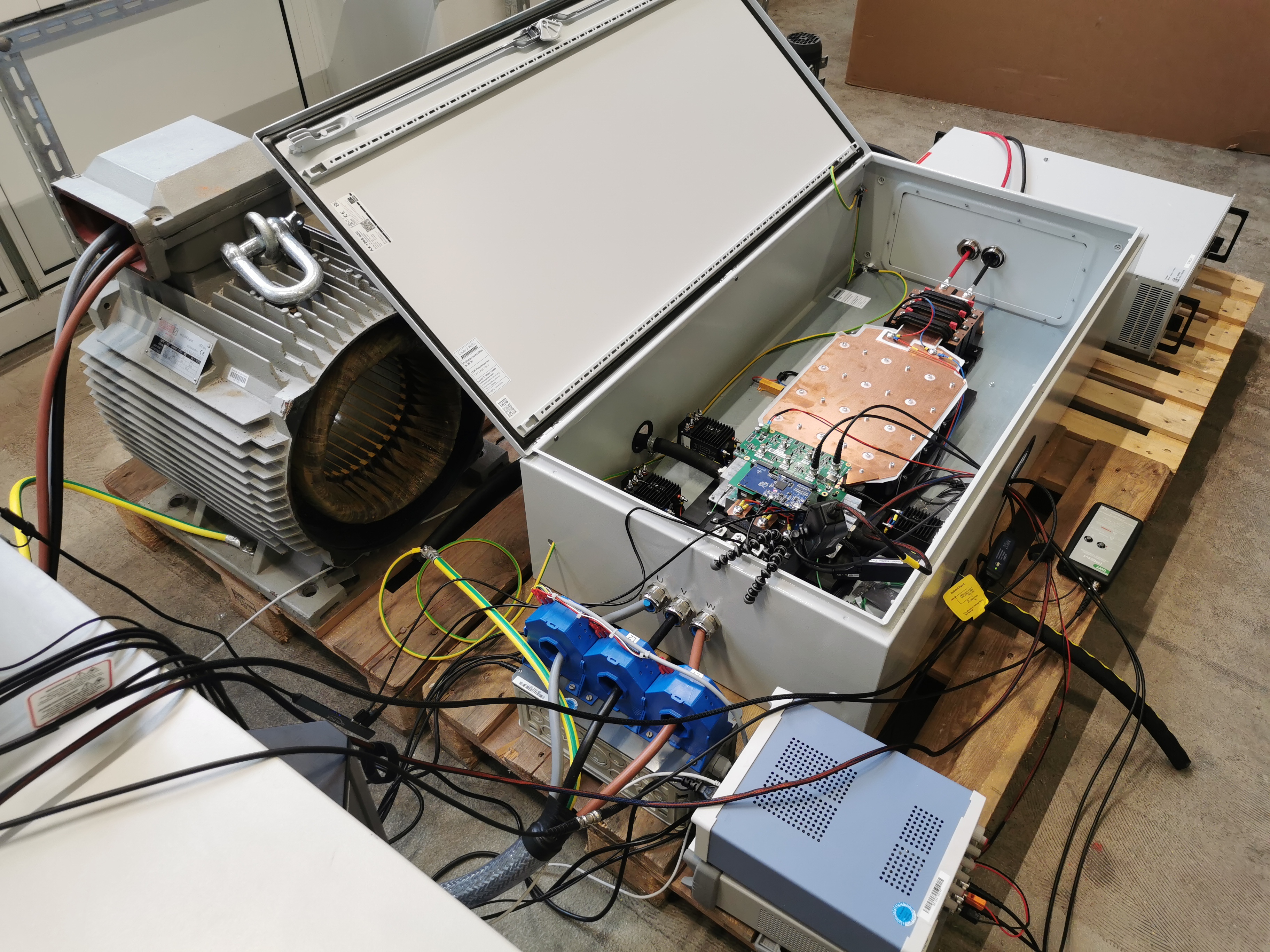
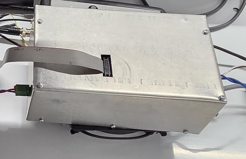
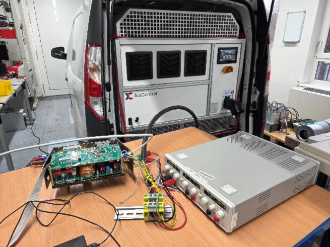 Verification of the PLC and the charging process via an EV Battery Emulator, which is normally used to verify the functionality and the energy metering of big DC charging stations.
from: AixControl GmbH
The Mobile In-Line Charger (MILCA) demonstrates a compact DC-charging solution for electric vehicles with a nominal charging power of approximately 2 kW. MILCA connects to a standard 230V house socket and has a CCS2 plug at the output for the connection to the electric vehicle. All components for DC charging, from contactors and insulation measurements to powerline communication(PLC), are integrated into a volume of approximately 2l. In this project, the focus was on the power electronics with a maximum volume of 1.5l. The MILCA has an integrated active power factor correction and a galvanically isolated DC/DC converter. The latest-generation of gallium nitride semiconductors make this compact charging electronics possible and might pave the way for future cars to dispense with build-in onboard chargers.
3D-design with low stray inductance connection of driver stages for GaN semiconductors.
First prototype realization of the MILCA.
Verification of the PLC and the charging process via an EV Battery Emulator, which is normally used to verify the functionality and the energy metering of big DC charging stations.
UC 1.6b - Medium power modular stationary charger
by: Francesco Porpora
from: E-Lectra s.r.l.
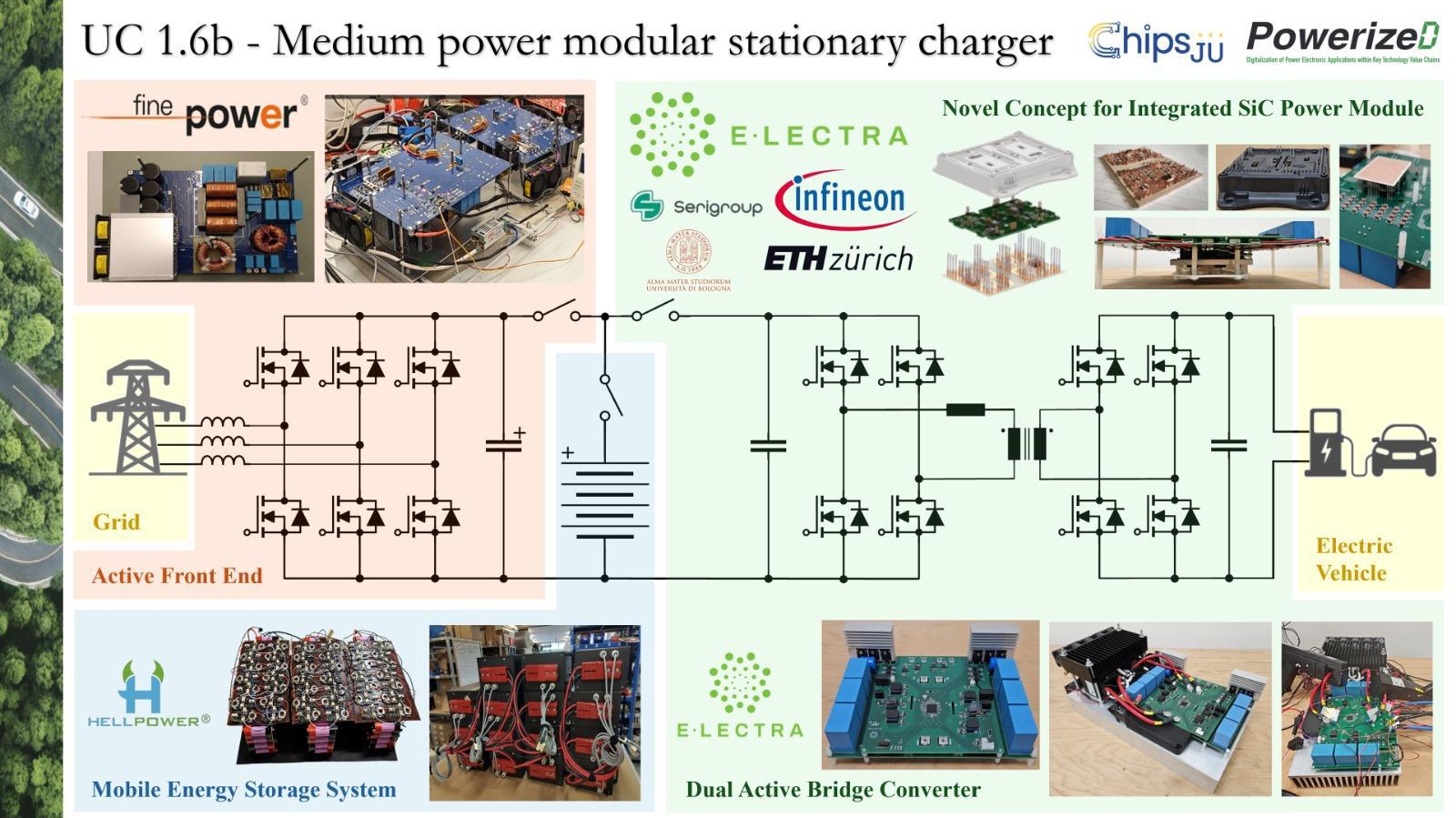
This use case developed devices and demonstrators for a medium-power bidirectional charging infrastructure for high-voltage electric vehicles, capable of enabling Vehicle-to-Grid (V2G) functionality. Specifically, considering a dual-stage conversion architecture with an integrated mobile and high-voltage battery pack, demonstrators were designed and experimentally validated for each main subsystem that composes the charging infrastructure.![]()
![]()
from: E-Lectra s.r.l.
This use case developed devices and demonstrators for a medium-power bidirectional charging infrastructure for high-voltage electric vehicles, capable of enabling Vehicle-to-Grid (V2G) functionality. Specifically, considering a dual-stage conversion architecture with an integrated mobile and high-voltage battery pack, demonstrators were designed and experimentally validated for each main subsystem that composes the charging infrastructure.
- Novel 1200-V SiC-based Intelligent Power Module (IPM) It integrates all the power devices of a Dual Active Bridge (DAB) converter and the related gate driver circuitry in a single compact housing, ensuring proper insulation between the primary and secondary sides. To enable precise junction temperature monitoring, a novel approach based on bondable NTC sensors directly positioned in close proximity to the SiC devices is adopted. Additionally, the IPM is also equipped with integrated shunt resistors and measurement circuitry for overcurrent protection and DC-link voltage monitoring. Two different substrate materials and technologies, including Alumina and IMS, are manufactured for the IPM to evaluate the electrical and thermal performances.
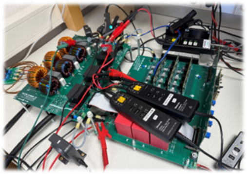
- Modular bidirectional DAB-based DC/DC solution with high-frequency insulation It is equipped with the IPM and designed to operate at a rated power of 25 kW and high switching frequency (100 kHz) within wide input (600÷950 V) and output (600÷900 V) voltage ranges, ensuring bidirectional power flows and efficiencies greater than 96% for most operating conditions (98.5% peak efficiency).
- Modular Active Front End (AFE) solution with bidirectional power flow capability Designed with a rated power of 25 kW, it ensures the applicability of high-power bidirectional AFE solutions in three-phase electric grids through a modular and compact design, capable to achieve an output power of 50 kW through parallelization. A dedicated control strategy is implemented to manage common-mode currents on the shared DC link, enabling system scalability.
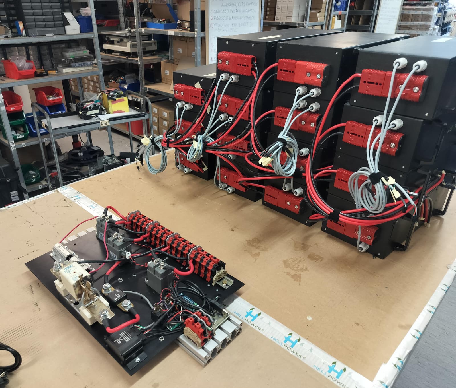
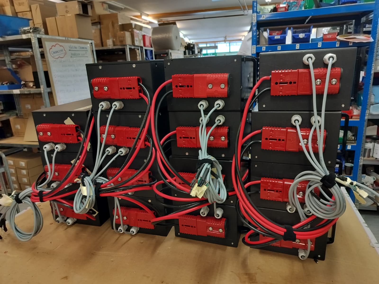
- Mobile buffer emergency battery system With a rated energy capacity of 20 kWh and 50 kW discharge capability, it is directly integrated within the charging infrastructure to provide backup energy for electric vehicle charging in case of grid outages and enabling ancillary grid services.
UC1.6c - Large Power Stationary Charger

by: Jos Schijffelen
from: POWER RESEARCH ELECTRONICS BV
As its main objective, PRE/Heliox has developed a 2x50kW DC/DC bidirectional power module instead of the originally planned 25kW module. Main reason: Increase in charging power and changes in charging standards such as CCS and MCS. The 100kW bidirectional isolated DC/DC focuses on the following: · Use for DC microgrid/DC bus power supply of 750V or ±750V (2 in series). It incorporates a newly designed DC droop control algorithm to ensure reliable and stable charging operation in both DC grid systems and in combination with Active Front Ends. (In line with CurrentOS). · Use of dual 50kW bidirectional isolated power block for 150-1000V CCS and 500-1500V MCS charging standards. Both standards have different safety philosophies regardingvoltage and isolation. CCS is basically anisolated network to PE and MCS is a symmetric balanced system to PE. The operating voltage always remains<1000V to PE. Our other objective is a smart integration of passive and active rectifiers. By combining these two rectifier technologies, we benefitfrom the advantages of both technologies. With the Active Front End (of 100kVA instead of 50kVA), the focus is on high charging efficiency, reactive power compensation and power quality improvement in a low cost passive rectifier MW solution.![]()
![]()
from: POWER RESEARCH ELECTRONICS BV
As its main objective, PRE/Heliox has developed a 2x50kW DC/DC bidirectional power module instead of the originally planned 25kW module. Main reason: Increase in charging power and changes in charging standards such as CCS and MCS. The 100kW bidirectional isolated DC/DC focuses on the following: · Use for DC microgrid/DC bus power supply of 750V or ±750V (2 in series). It incorporates a newly designed DC droop control algorithm to ensure reliable and stable charging operation in both DC grid systems and in combination with Active Front Ends. (In line with CurrentOS). · Use of dual 50kW bidirectional isolated power block for 150-1000V CCS and 500-1500V MCS charging standards. Both standards have different safety philosophies regardingvoltage and isolation. CCS is basically anisolated network to PE and MCS is a symmetric balanced system to PE. The operating voltage always remains<1000V to PE. Our other objective is a smart integration of passive and active rectifiers. By combining these two rectifier technologies, we benefitfrom the advantages of both technologies. With the Active Front End (of 100kVA instead of 50kVA), the focus is on high charging efficiency, reactive power compensation and power quality improvement in a low cost passive rectifier MW solution.
UC 1.7 - System of Systems - Demo A

by: Kaspars Ozols
from: ELEKTRONIKAS UN DATORZINATNU INSTITUTS
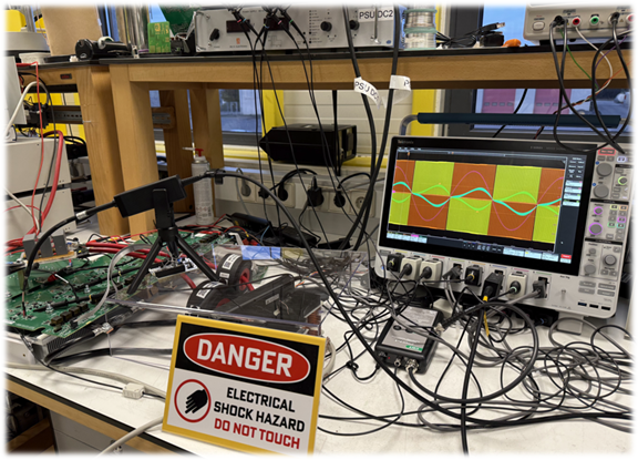
As one of the UC1.7 demonstrators, this demonstrator showcases an additional Differential Privacy (DP) protection module for the Federated Learning (FL) system, highlighting the benefits of enhanced privacy. The demonstrator illustrates the AI module’s training process using the CALCE dataset to estimate a battery’s Remaining Useful Life (RUL). The DP module is implemented with the OPACUS DP library and can be toggled "on" or "off". Multi‑client FL training is simulated with separate processes within a single Docker container. Protection levels can be monitored via epsilon values (the ε‑privacy budget), which the system calculates at the end of each training cycle.
from: ELEKTRONIKAS UN DATORZINATNU INSTITUTS
As one of the UC1.7 demonstrators, this demonstrator showcases an additional Differential Privacy (DP) protection module for the Federated Learning (FL) system, highlighting the benefits of enhanced privacy. The demonstrator illustrates the AI module’s training process using the CALCE dataset to estimate a battery’s Remaining Useful Life (RUL). The DP module is implemented with the OPACUS DP library and can be toggled "on" or "off". Multi‑client FL training is simulated with separate processes within a single Docker container. Protection levels can be monitored via epsilon values (the ε‑privacy budget), which the system calculates at the end of each training cycle.
UC 1.7 - System of Systems - Demo B
by: Tobias Schafberger
from: Ostbayrische Technische Hochschule (OTH) Amberg-Weiden
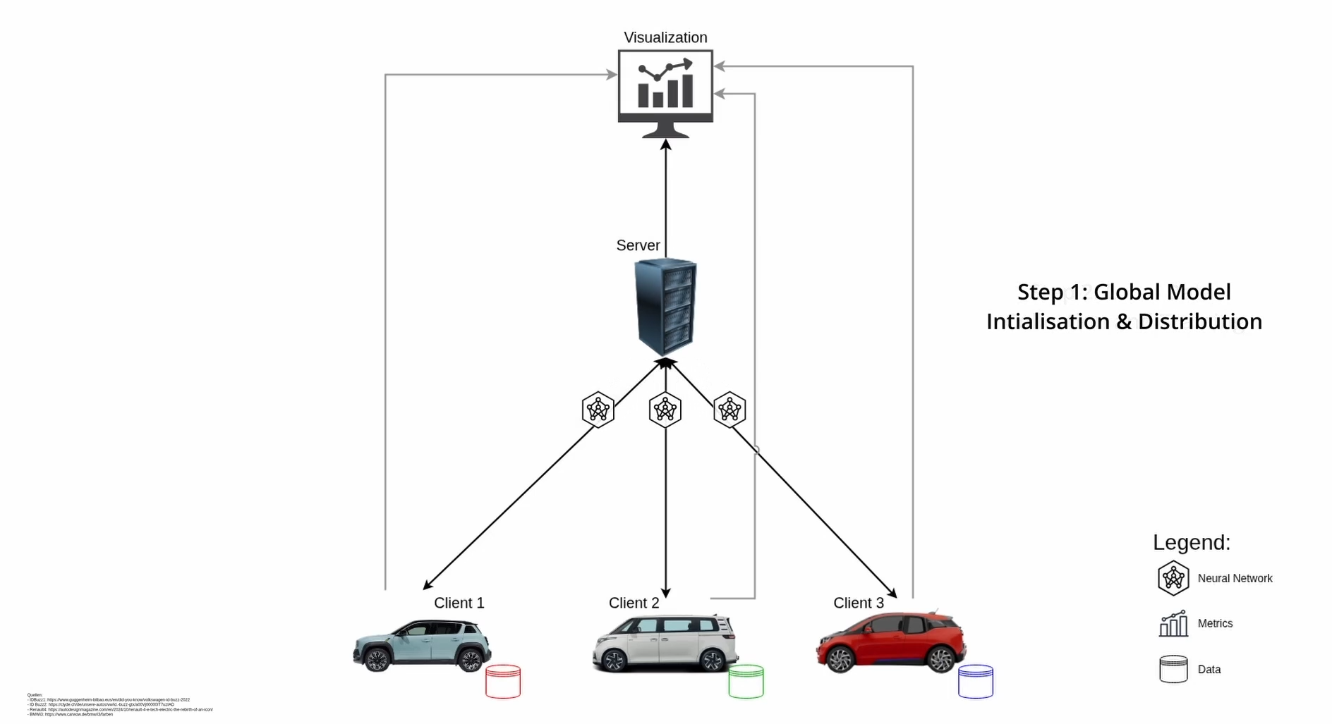
One demonstrator of UC1.7 will highlight the benefits of Federated Learning, applied to estimate the Remaining Useful Life (RUL) of batteries using data from a simulated EV fleet. To achieve this, meta-models for the EV and its battery are created to generate battery ageing data. This data is then processed and used to train AI models through Federated Learning. The complete pipeline—from data generation and processing to training with FL—will be deployed both on edge devices and on a high-performance computer. Finally, key metrics and insights from the FL process will be presented in an interactive dashboard.
from: Ostbayrische Technische Hochschule (OTH) Amberg-Weiden
One demonstrator of UC1.7 will highlight the benefits of Federated Learning, applied to estimate the Remaining Useful Life (RUL) of batteries using data from a simulated EV fleet. To achieve this, meta-models for the EV and its battery are created to generate battery ageing data. This data is then processed and used to train AI models through Federated Learning. The complete pipeline—from data generation and processing to training with FL—will be deployed both on edge devices and on a high-performance computer. Finally, key metrics and insights from the FL process will be presented in an interactive dashboard.
UC 1.7 - System of Systems - Demo C
by: Konstantina Karathanasopoulou
from: Harokopio University of Athens
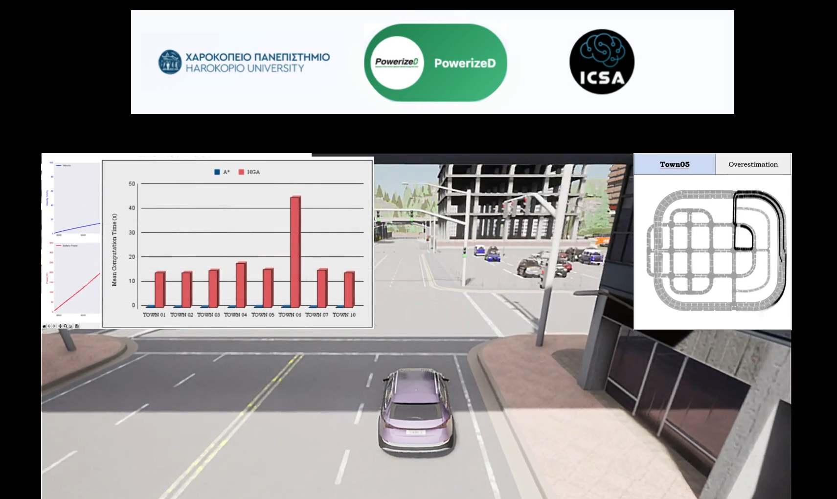
The CARLA-based demo for PowerizeD Use Case 1.7, developed by Harokopio University of Athens, provides a novel framework to quantify how path-planning choices impact vehicle energy expenditure. By utilizing a Hybrid Genetic Algorithm (HGA) andan offline energyestimation model with a 10% standard mean deviation, the work optimizes routes based on energy, duration, and distance. For more details on our research, please visit our website: https://icsa.hua.gr/
from: Harokopio University of Athens
The CARLA-based demo for PowerizeD Use Case 1.7, developed by Harokopio University of Athens, provides a novel framework to quantify how path-planning choices impact vehicle energy expenditure. By utilizing a Hybrid Genetic Algorithm (HGA) andan offline energyestimation model with a 10% standard mean deviation, the work optimizes routes based on energy, duration, and distance. For more details on our research, please visit our website: https://icsa.hua.gr/
UC 2.1 - Flow battery power electronics
by: Jiajun Cen
from: Aqua Battery
AquaBattery is deploying a 5 kW / 50 kWh pilot system at Deltares in Delft (NL) to demonstrate its innovative saltwater flow battery based on table salt within the PowerizeD EU project. The installation is directly connected to Deltares’ research facilities. It is designed to test and learn how long-duration energy storage can enable renewable integration in a behind-the-meter setting. As part of PowerizeD, the pilot acts as a real-world validation site for a novel high-efficiency DC-DC converter tailored for asymmetric charge and discharge profiles, while also serving to test and refine advanced control methodologies aimed at improving round-trip efficiency, extending system lifetime, and enhancing overall reliability

UC 2.3 - LED driver and LV DC distribution grid
by: Eugen De Mol
from: SIGNIFY NETHERLANDS BV
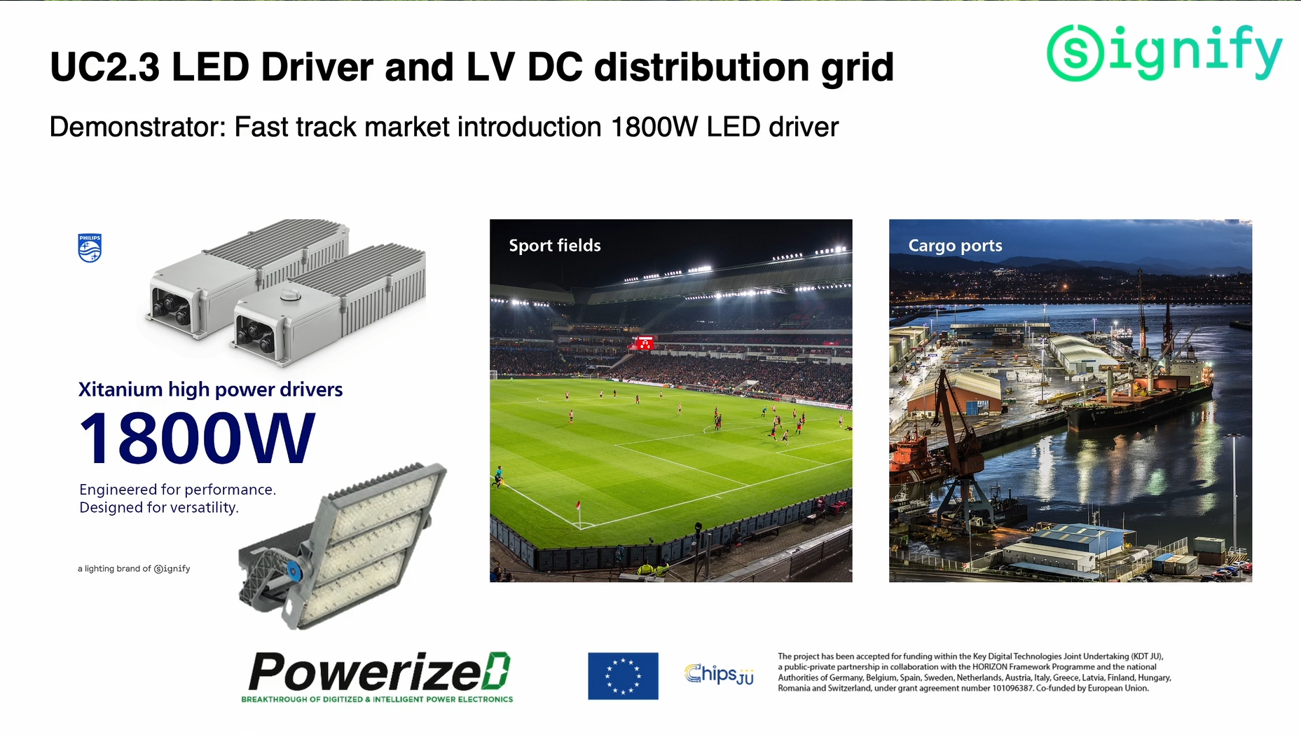
The competitive lighting market landscape requires the fast introduction of a first generation 1800W LED driver. Therefore, next to working on building blocks for next generation LED drivers, already during the PowerizeD project, Signify will develop the first 1800W LED driver with an electrical and thermal performance beyond best-in-class LED drivers currently in the market for this application field. This product, called Xitanium 1800W, is to be fully released early 2026.
Target applications for the Xitanium 1800W are indoor and outdoor sport fields, but also large areas like airports and cargo ports.
from: SIGNIFY NETHERLANDS BV
The competitive lighting market landscape requires the fast introduction of a first generation 1800W LED driver. Therefore, next to working on building blocks for next generation LED drivers, already during the PowerizeD project, Signify will develop the first 1800W LED driver with an electrical and thermal performance beyond best-in-class LED drivers currently in the market for this application field. This product, called Xitanium 1800W, is to be fully released early 2026.
Target applications for the Xitanium 1800W are indoor and outdoor sport fields, but also large areas like airports and cargo ports.
UC 2.4 - Home and mobile PV with storage
by:Georg Heiland
from: FINEPOWER GMBH
The demonstrator shows an improved battery storage system for private households, including power electronics and a low-voltage battery. The project-related innovations are an efficiency increase, extended functionality and increased power density. The efficiency is increased by an additional hardware auxiliary circuit and corresponding software-created control method, the functionality should be extended in terms of grid and load analysis as well as state of health analysis of the battery, improving by special control algorithms in terms of healthy charging and discharging current waveforms. Besides that, the power density of the whole power electronics unit is increased by designing a compact heatsink structure applicable to 3D metal printing technology.

UC 3.1b – Intelligent gate driver for industrial inverter

by: Sebastian Rode and Dirk Rudolph
from: TUD – Dresden University of Technology
The UC3.1b demonstrator addresses advanced gate driver concepts for industrial inverters. It enables flexible dv/dt control and current balancing in parallel power devices, supporting both IGBTs and SiC MOSFETs. Two complementary methods – a controllable gate-emitter voltage source and a constant current source – are demonstrated. Furthermore, different approaches for current sensing are integrated and validated, including shunt-based measurement and a novel AMR sensor. Together, these developments contribute to improved robustness, efficiency and flexibility in next-generation industrial drives.

UC 3.2 - Hyper-sensorised digital drive - Demo A
by: Jesús Cantero Martínez
from: FAGOR AUTOMATION S COOP
Buck Converter demonstrator: It is a power converter that dynamically regulates the DC bus voltage via CNC control to match the operational requirements of the motor. Inverter demonstrator It is a modular speed controller that integrates a high-resolution digital current sensing acquisition system, coupled with an optimized decimation algorithm.
UC 3.2 - Hyper-sensorised digital drive - Demo B
by: Jesús Cantero Martínez
from: FAGOR AUTOMATION S COOP
The developed framework enables the prediction of the remaining useful life of electronic devices by leveraging run-to-failure data and advanced machine learning techniques. It offers a user-friendly interface to configure models such as recurrent neural networks and mixture density networks, supports ensemble learning with automated optimization, and provides recommendations through fuzzy logic inference. In addition, it allows transfer learning to improve efficiency and accuracy, and can deliver online, real-time predictions via a REST API, making it a versatile tool for prognostics and health management in power electronics.